Your M3 screw won't go in. You measure the hole: 2.9 mm, on a model you drew at 3.0. So you open the slicer, find a hole compensation slider, push it to +0.2 and move on. Sometimes that works. Sometimes the hole is fine at 3 mm and still tight at 10 mm, or round on the plate and visibly octagonal under a flashlight. That's because a short hole isn't one error. It's three, and they scale differently with diameter, which is why a single slider can only ever fix one of them.
| Symptom / Value | What It Means |
|---|---|
| Small holes (under 6 mm) are proportionally worse than big ones | Mesh facets, not the printer |
| Hole is visibly polygonal, with flat sides at 3–5 mm | Low-resolution mesh export |
| Holes run 0.1–0.2 mm under and bosses run 0.1–0.2 mm over | Bead squish / over-extrusion |
| A 50 mm+ bore is 0.2 mm under even though small holes fit | Shrinkage scaling with diameter |
| Outside dimensions are dead-on but holes are 0.3 mm+ under | Coarse mesh or inner-wall flow, not global scale |
| Hole is oval, long axis along X or Y | Mechanical: belts, ringing or steps, not a slicer setting |
Error One: The File Already Shrank It
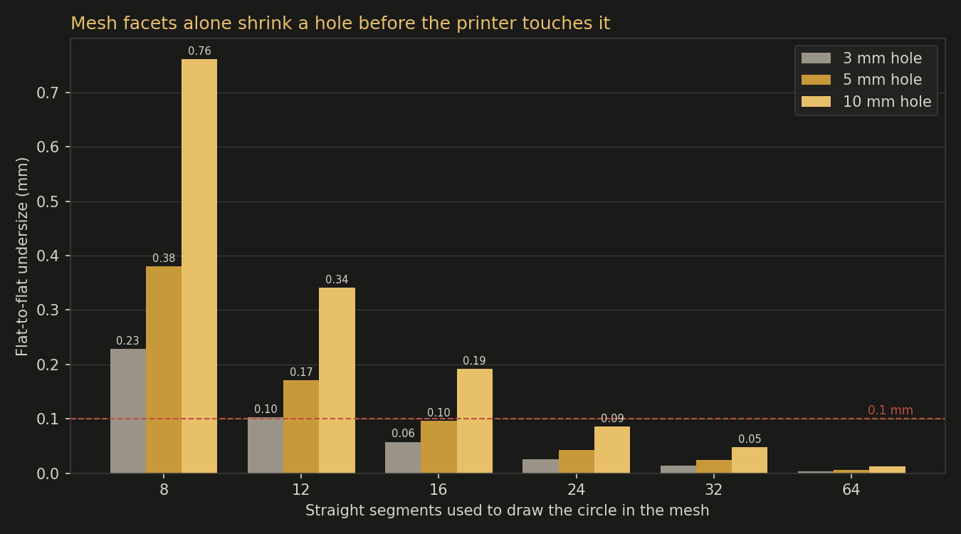
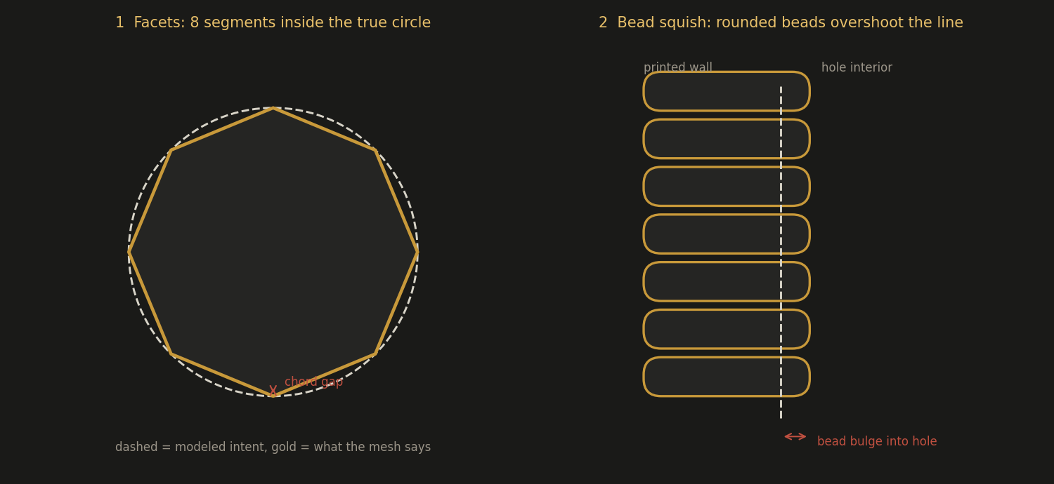
STL files describe curves as flat segments. A circle drawn with 8 segments, inscribed so the corners touch the true circle, measures D × cos(180°/n) across the flats. A 5 mm hole at 8 segments is 4.62 mm across before the printer moves at all. At 16 segments it's 4.90 mm, at 32 it's 4.98 mm, at 64 it's 4.99 mm.
Most CAD exports are fine. Hand-built and quick-modeled meshes are where it bites. OpenSCAD's defaults ($fa = 12, $fs = 2) draw a 2.5 mm radius circle with about 8 segments, so a script that never sets $fn ships octagonal M5 holes. If you can see flats in the slicer preview, you've found error one. Set $fn to 64 or export at a 0.01 mm chord tolerance, and re-measure before touching any printer setting.
Error Two: The Bead Overshoots the Line
Slicers model an extruded line as a rounded bar. The real bead, squished against the layer below and slightly over-extruded, bulges past that idealized edge. On an outside wall the bulge makes a boss too big. On a hole wall the same bulge points into the hole. The typical result is 0.1–0.2 mm of diametral error, with opposite signs on outside and inside features. If bosses measure over and holes measure under by roughly the same amount, this is your error.
That's why flow comes before compensation. Trim extrusion a few percent and both numbers move toward nominal. Stack a hole offset on an over-extruded print and you're compensating for something you could have removed. Slower, steadier inner walls (30–60 mm/s) also keep the bead width consistent through small-radius curves.
Error Three: Shrinkage Grows With Diameter
Plastic contracts as it cools, and a bore shrinks with the material around it. At 0.5% shrinkage a 5 mm hole loses 0.025 mm, which is below the noise. A 50 mm bearing seat loses 0.25 mm, bigger than the other two errors typically are. ABS and ASA shrink more than PETG-family materials, and PCTG sits at the low end, so large bores land closer to the model on the first try. If only your big bores are off, scale that feature, not the whole part.
DiagnosisIsolate Which One You Have
Print a coupon with vertical holes at 3, 4, 5, 6, 8 and 10 mm. Measure each with drill bits or pin gauges, because calipers on a small hole lie. Then read the pattern:
- Worst on the smallest holes: facets
- A flat 0.1–0.2 mm across every size, with bosses over by the same amount: bead squish
- Error that keeps climbing past 30 mm: shrinkage
- Oval holes, or error that changes with X versus Y: mechanical, go fix belts first
What Three Errors Look Like on One 5 mm Hole
Take a 5 mm hole exported at 16 segments. The mesh alone puts the flats at 4.90 mm, a 0.10 mm loss. Add a 0.15 mm bead bulge and the printed hole measures about 4.75 mm. On a 5 mm hole, shrinkage adds roughly 0.02 mm more, so you land near 4.73 mm. An M5 shank at 5.0 mm is now interference, not a clearance fit, and no amount of belt tension changes that.
Now apply a lone +0.1 mm slicer offset, which is the most common fix. It recovers 0.2 mm of diameter and brings the hole to roughly 4.93 mm, so it still binds, while the same offset on a 10 mm hole that only had bead error leaves it near 10.05 mm. One number cannot be right for both because the mesh error does not scale with the offset. Fix the export to 64 segments instead, and the same hole needs only the small bead correction, which transfers to every other hole on the part.
The practical point: measure the coupon once, split the error into the three buckets above, and write down the resulting flow and offset next to the material profile. When you change nozzle, material or even spool brand, rerun the coupon. It takes one short print and saves a reprint of every part with a fastener in it.
The FixFix Them in Order
Order matters because each fix changes what the next one needs to correct.
- 1Fix the mesh.Finer export, $fn of 64 or more, or polyholes: a polygon with radius r / cos(180°/n) so the flats land on the true diameter.
- 2Calibrate flow.Print a single-wall cube and measure the wall with calipers. Set extrusion multiplier from that, not from a hole.
- 3Set hole compensation last.Cura calls it Hole Horizontal Expansion and OrcaSlicer calls it X-Y hole compensation. Both are offsets applied to the outline, so a 0.2 mm diametral error needs about 0.1 mm. Confirm on the coupon, since slicers differ.
- 4Design clearance by function.ISO 273 normal-fit clearance holes are 3.4 mm for M3, 4.5 mm for M4 and 5.5 mm for M5. Tapped or self-tapping holes want a smaller pilot, tested on your printer.
- 5Orient with intent.Horizontal holes sag at the top edge. Teardrop them, or accept a slightly oval top.
PCTG is the confident pick when hole dimensions matter. Its modified CHDM structure keeps moisture absorption around 0.15%, lower than PLA and a real step up from standard PETG, so the offset you calibrate on day one is still right at the end of the spool. Wet filament changes bead width, and bead width is error two.
When a part has to take a bolt, a bearing or a press-fit pin the first time, the number belongs on the printed part, not in your slicer profile. See the realistic capabilities breakdown for where those limits sit.
Holes That Match the Drawing
Every DuffAM part is measured against a coupon and compensated per feature, so the bore fits the bearing on part one and part fifty.
Order Direct at DuffAM →If holes drift undersized over weeks on the same profile, a worn orifice is the other suspect.
Elephant's Foot Isn't Cosmetic — It's a Tolerance ProblemThe same squish-and-bulge mechanism, measured at the base of the part instead of inside a hole.