
The top of the print looks like a pillow: a grid of soft bumps with little pits between them, sometimes with real holes where you can see the infill. The usual diagnosis is under-extrusion, so the usual fix is raising flow or temperature. That makes the bumps worse, because the top surface was never short of plastic. It was short of support. The first top layer is a bridge across the gaps in your infill, and it sagged.
| Symptom / Value | What It Means |
|---|---|
| Bumps and pits repeat in a regular grid | The grid pitch is your infill line spacing — a bridging problem, not a flow problem |
| Walls and bottom layers look solid and well-fed | True under-extrusion shows on every surface, not only the top |
| Worse on the 5–10% infill version of the same part | Wider gaps to span; pillowing scales with gap width |
| Roughly 3 top layers (0.6 mm at 0.2 mm layers) | Not enough skin to bury the sag |
| Raising flow gave you ridges and blobs, not a fix | Confirms plastic volume was never the issue |
| Top layers printed with part-cooling fan under ~50% (PLA) | Bridge stays molten and droops before it freezes |
Read the Pattern Before Touching a Setting
Under-extrusion is a path-following defect: gaps along the line direction, visible on walls, bottom layers, and the top alike, usually worse at speed. Pillowing is a geometry-following defect: the bumps sit over the voids in the infill, so their spacing matches your infill line spacing. Measure the pitch with calipers. If it matches your infill spacing, nothing in the extruder is wrong. If the walls also look starved, stop reading this and check your hotend's flow ceiling instead.
The PhysicsThe Top Skin Is a Bridge, and Bridges Sag
Below the top skin, the infill is a field of lines with air between them. The first top layer has to cross each gap with nothing underneath it. Hot plastic over a gap droops under its own weight until it freezes. A wide gap droops more, a hotter extrusion droops longer, and a weak fan lets it stay soft longer. Each following layer fills in some of that dip, but only some, and if there aren't enough layers left the dip survives to the surface.
The gap is easy to estimate. For a line-based infill with a 0.42 mm line width, spacing is about line width divided by density, and the open gap is spacing minus one line width.
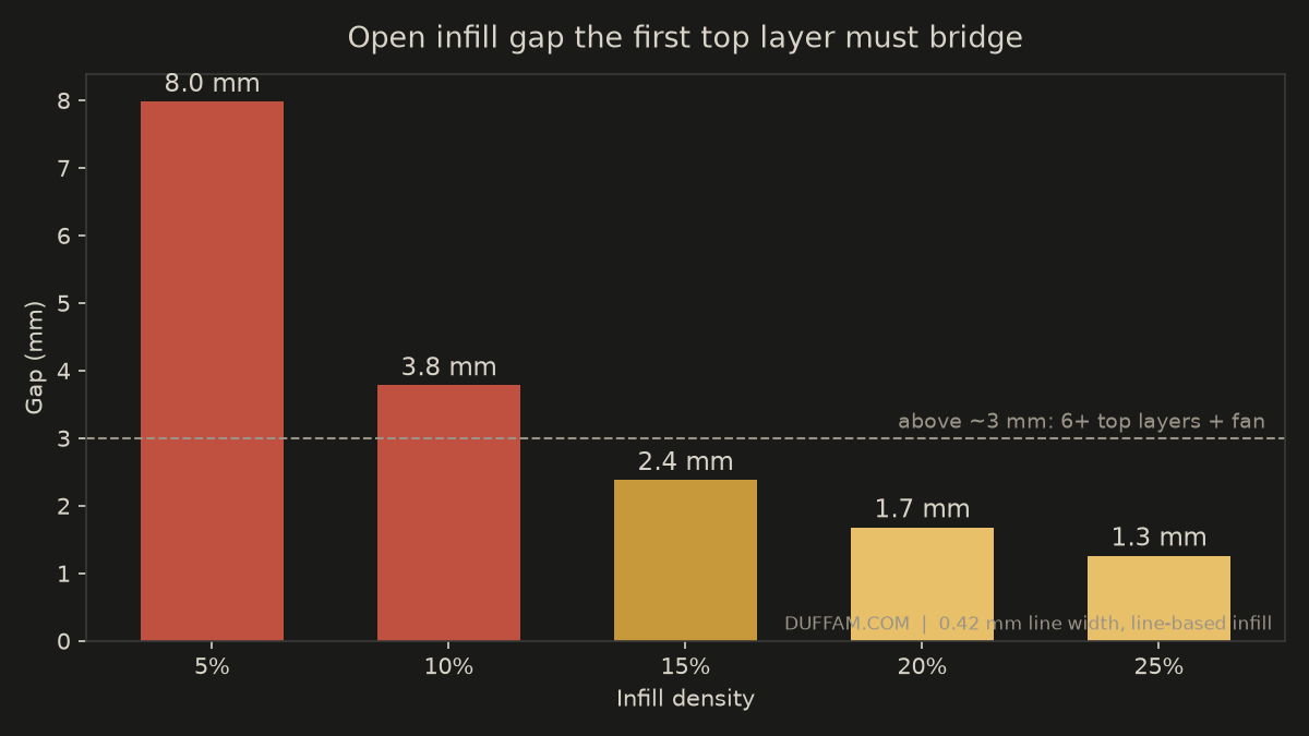
At 20% infill the open gap is only about 1.7 mm and almost anything bridges it. At 10% it is about 3.8 mm, and at 5% about 8 mm, which is where a default three-layer skin has no chance.
The FixIn This Order
- 1Add top layers to fit the gapAim for at least 1.0 mm of top skin at 15–20% infill (five layers at 0.2 mm), and 1.2 mm or more at 10%. Set it by thickness if your slicer allows, so layer height changes don't silently thin it.
- 2Fan up on the top layersPLA wants 100% fan on the bridging layer. PETG and PCTG tolerate roughly 50–70% before layer bonding suffers, and top layers are the place to spend it. If the slicer has a separate bridge fan setting, use that.
- 3Slow and cool the first top layerA slightly cooler nozzle (5–10°C below your normal print temperature) lets the bridge freeze sooner, as long as you stay in the filament's good range. Reduce the top-layer speed so the fan has time to work.
- 4Raise infill only if the part needs itGoing from 10% to 15% shrinks the gap from roughly 3.8 mm to 2.4 mm. If you don't need the weight savings, that costs less than another layer or two of skin.
- 5Ironing for the last mileIroning passes with a very low flow (about 10–15%) can level small dimples, but it can't hide a 1 mm sag. It finishes a good top surface; it doesn't rescue a bad one.
Skin Thickness by Infill Density
| Infill | Open gap | Top layers (0.2 mm) | Top skin |
|---|---|---|---|
| 25% | ~1.3 mm | 4 | 0.8 mm |
| 20% | ~1.7 mm | 4–5 | 0.8–1.0 mm |
| 15% | ~2.4 mm | 5 | 1.0 mm |
| 10% | ~3.8 mm | 6 | 1.2 mm |
| 5% | ~8 mm | 8+ | 1.6 mm+ |
These are starting points from the gap geometry, not guarantees. Dense-pattern infill like gyroid bridges slightly differently from straight lines, so print a small flat test block before committing a long job.
PCTG is a good fit here. With moisture uptake around 0.15% (lower than PLA, a clear step up from PETG) it doesn't add the bubbling and rough texture that wet filament piles on top of a pillowed surface. If you can't tell whether your top surface is pillowing or just wet filament, dry the spool first; pillowing keeps its grid pattern either way.
Nearly every pillowed top surface is fixed by two things the slicer already exposes: more top layers and more fan on them. Before you touch flow, measure the pitch of the bumps and see if it matches your infill spacing. DuffAM sets top skin thickness per part from its infill density rather than from a default profile — see how that fits into our approach in the process breakdown on the home page.
Top Surfaces That Don't Look Like Pillows
DuffAM sets top-skin thickness and top-layer cooling per part based on its infill, so flat faces come out flat instead of dimpled.
Order Direct at DuffAM →Choosing infill density and top layer count together: what each one actually controls.
Your Printer Isn't Slow — Your Hotend Is StarvingIf the walls look starved too, this is the real under-extrusion: a flow ceiling, not a top-layer problem.