
Somebody's bracket snapped at the screw hole, so they went into the slicer, bumped infill from 20% to 100%, and reprinted. It still snapped at the screw hole. That's not a rare outcome — it's the default outcome, because infill percentage was never the setting standing between that part and failure. For the load cases most desktop parts actually see — bending, impact, a screw pulling against a boss — the walls of the part are doing almost all the structural work, and infill is filling space, not carrying stress.
| Symptom / Value | What It Means |
|---|---|
| Snapped at a screw boss, hinge point, or thin feature — infill was 50%+ | Wall count at that feature, not infill, was the limit |
| Cracked cleanly across a flat face under bending or a drop | Perimeter shell too thin for the load path — a wall problem |
| Crushed, dimpled, or felt hollow under sustained weight | Infill density or pattern — this is the actual infill case |
| Went from 20% to 100% infill, the break looked the same | Confirms infill was never the variable |
| Top surface sagged where something rested on it | Top layer count too low, not infill percentage |
| Held fine at 15% infill but failed after switching infill patterns | Pattern orientation relative to load, not density |
Why 100% Infill Feels Like the Safe Answer
Infill percentage is the one strength-adjacent number every slicer puts front and center, so it becomes the lever people reach for first. The mental model is reasonable-sounding: more plastic inside the part must mean a stronger part. It's just not how FDM parts actually fail. A part under bending or impact load fails where stress concentrates and where the cross-section resists least — almost always at the outer wall, a boss, or a thin rib — not in the sparse interior lattice sitting quietly in the middle of the part doing very little until you're already past the point of no return. Push infill from 20% to 100% on a part that snapped at a mounting hole and you've added print time, weight, and material cost without touching the thing that actually broke.
The PhysicsWhat Actually Carries the Load
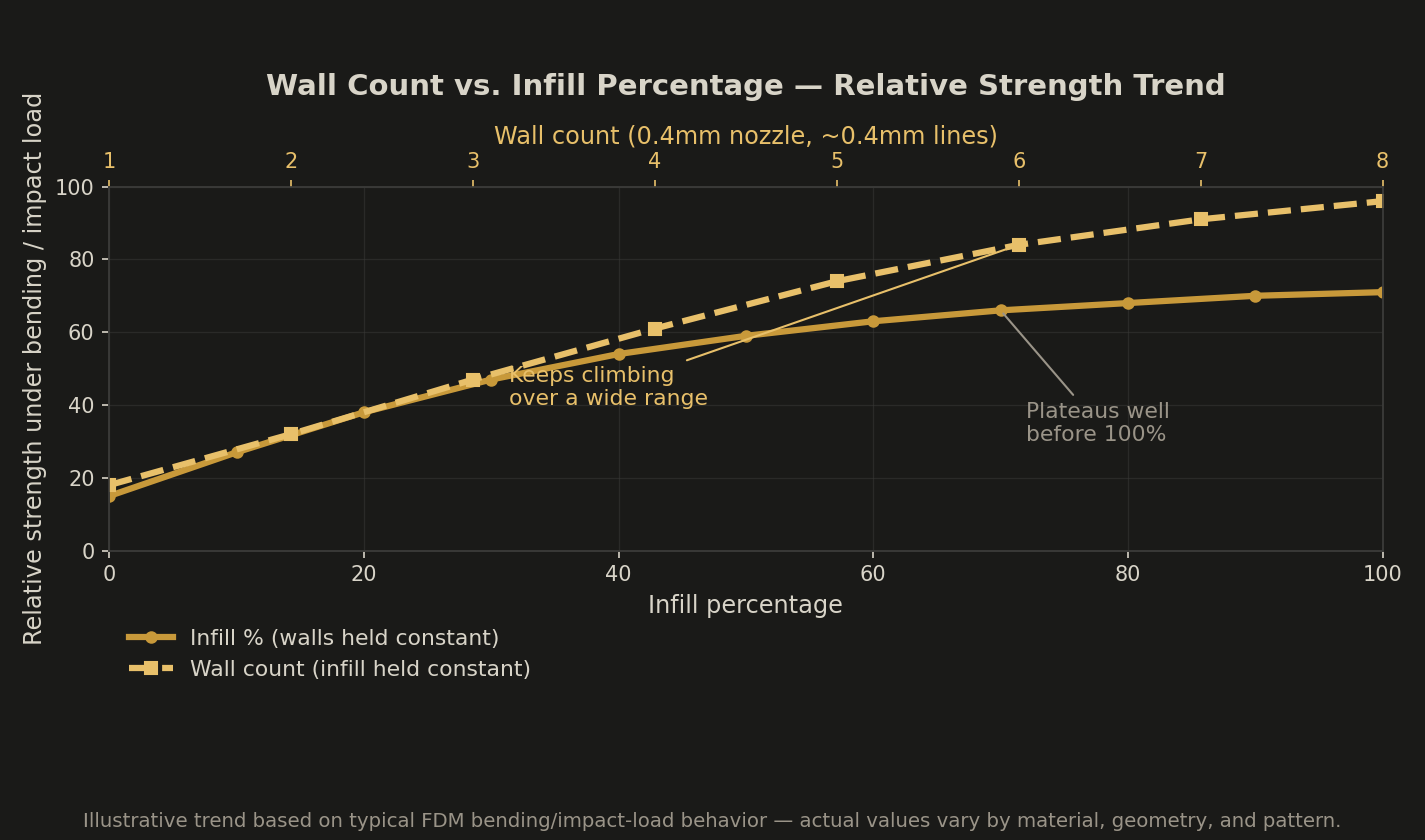
Walls print as continuous, solid perimeters that run the full height of the part, laid down in an unbroken loop each layer. That geometry is exactly what you want resisting bending and tension — it's solid, it's oriented along the load path, and each wall layer bonds to the one above it the same way any well-printed vertical section does. Infill is a different animal: a sparse lattice of short struts that only touch each other and the walls at isolated points. Those strut junctions are where infill actually fails, and they're weaker than a continuous wall by a wide margin because there's far less bonded surface area holding them together. Add infill percentage and you're making that lattice denser, not turning it into a wall. The strength gain from more struts plateaus fast, while the strength gain from more walls stays close to linear over a much wider range, because you're adding solid, continuous shell instead of more low-density lattice.
Where Infill Percentage Actually Matters
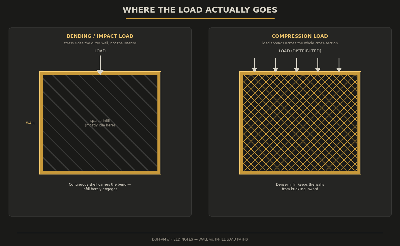
None of this means infill percentage is decorative. It matters most when the load is compressive and distributed across the whole cross-section rather than concentrated at an edge or a hole — a foot standing on the print, a spacer under sustained clamping force, a housing that gets sat on. In pure compression, the infill lattice is what keeps the walls from buckling inward, and density does buy real resistance there. It also matters for anything with a large unsupported top surface: too little infill under a wide flat top skin lets that skin sag or dimple under its own printed weight before it's even loaded, which gets misread as a top-layer problem when it's actually a support-density problem underneath.
Wall Problem
- Fails at a screw boss, hinge, or thin rib
- Cracks along a flat wall under bending/impact
- Snapped cleanly, high infill made no difference
Infill Problem
- Crushes or deforms under steady compressive load
- Feels hollow or spongy when tapped
- Flat top surface sags before it's even loaded
Wall Count and Infill by Use Case
| Use Case | Wall Count | Infill % / Pattern | Notes |
|---|---|---|---|
| Decorative / prototype | 2 (0.8mm) | 15% grid | Fine — nothing here is under real load |
| Everyday functional (clips, mounts, brackets) | 4 (1.6mm) | 20–25% gyroid | Biggest strength jump of the whole table |
| Load-bearing / repeated-cycle (snap-fits, structural brackets) | 5–6 (2.0–2.4mm) | 30–40% gyroid or cubic | Add 2–3 extra perimeters locally around screw bosses |
| Compression-dominant (feet, spacers, sat-on housings) | 3–4 (1.2–1.6mm) | 40–60% cubic or gyroid | The one case where raising infill % is the right first move |
| Wide flat tops under load | — | Top layers 6–8 (~1.2–1.6mm at 0.2mm layer height) | Fixes sag before touching infill at all |
Reading Where It Broke Before You Change a Setting
How to Actually Test It
- 1Print two identical test brackets. Same geometry, one at 2 walls / 20% infill, one at 5 walls / 20% infill — infill held constant, only wall count changes.
- 2Load them the same way. Clamp or hang the same increasing weight until each fails, or snap them by hand at the same point.
- 3Compare where they broke. If the 5-wall part took meaningfully more force before failing, wall count was the limiting variable — not infill.
- 4Repeat with infill, walls held constant. Print 20% and 60% infill at the same wall count. If the difference is small under a bending/impact test, you've confirmed infill wasn't your lever.
- Increase wall count first for anything under bending, impact, or a screw load
- Reserve infill percentage increases for compression-dominant parts
- Add local perimeters around bosses and holes instead of raising global infill
- Raise top layer count separately from infill when a flat top surface sags
- Switch to gyroid or cubic infill before reaching for more density in either pattern
If you've already got wall count and infill dialed in and a part still creeps or sags under sustained load, check the material before the settings. PLA visibly creeps under continuous stress at room temperature — that's the material, not the count of walls or the infill under them. PCTG resists that kind of long-term deformation better than PLA and prints with more consistent layer bonding than PETG, with a moisture pickup around 0.15% — a step up in stability from PETG and lower than PLA's own moisture uptake. For a part that has to hold a load for months, not just survive one drop test, that material difference can matter more than another 10% of infill.
Most of the parts that fail at 100% infill were never going to be saved by more infill — they needed a different wall count, a local reinforcement, or a different material, and the settings panel buried that answer under the one number every slicer puts at the top. DuffAM locks wall count and infill per part by load case as part of the standard process — see how that fits into the bigger picture in the process breakdown on our home page.
Parts Built for the Load They'll Actually See
Every DuffAM part gets its wall count and infill set by load case, not a default slicer profile, so it doesn't fail at the screw hole because the interior was optimized for the wrong number.
Order Direct at DuffAM →